
For 7 up to max 16 inputs
DIN rail cabinet
h:11 cm, d 7,5 cm, w 10 cm
max 6 inputs/outputs
Small size DIN rail cabinet
h:11 cm, d 7,5 cm, w 2,7 cm
www.ekopower.nl copyright
2006-2019 version
12 sept 2019 ONLY for version 12 firmware!
|
|
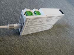
iBOX (Full version) For 7 up to max 16 inputs DIN rail cabinet h:11 cm, d 7,5 cm, w 10 cm |
|
Mini iBOX-2S for max 6 inputs/outputs Small size DIN rail cabinet h:11 cm, d 7,5 cm, w 2,7 cm |
MANUAL iBOX / iBOX-2S Datalogger System
with SMART ONLINE OPTIONS
General information
-
information at web page about iBOX dataloggers
Refer also to:
- application note
for low power iBOX and with switched 4G Router
- application note for
WiFi/ 4G Router networks
- Compact
4G Router type 4G100
* New 4G Routers,
which can be powered via 6V Solar Power supply: 4G Industrial Router R700
NEW EKO-options:
* ULTRA LOW POWER version available for battery
operation at remote sites
* 4G router with EKO switch in order to save energy and less HF electromagnetic
fields:
4G Router switch ONLY on during transfer of data
* Small low cost WiFi module available, including EKO switch in order to save
energy and WiFi Fields
Introduction
QUICK INSTALLATION INSTRUCTIONS:
- Hardware connections must be made according
to the supplied label at the iBOX (and pdf file)
- Install the (send or downloaded) control software version 12 (supplied
in zip file)
- Copy the supplied configuration file into the software folder
- Start the software and open the supplied configuration nr
- Modify the settings according to your project (like intervals, server ip
address, folder etc).
- Prepare the supplied TRANSCEND (u)SD Card (max 2GB) with specific settings and put into
the iBOX
- For connections and specific information refer the label at the iBOX / iBOX-2S
system
- Connect the power and the system will start.
After connecting power the GREEN LED should flash and will repeat flashing
(operation OK)
If the LED is constantly ON, reboot the system:
1) disconnect and reconnect power or 2) take out the memory
card and insert again!
If the LED is flashing each minute several times the uSD Card is
not correct: prepare again with right
configuration nr.or replace the memory card.
- Connect the iBOX (default ip address 192.168.0.200) to a LAN network eg
with
router address (gateway) 192.168.0.1 (must be in the same range as the
datalogger)
The iBOX has a static adjustable ip address (no DHCP for easy port
forwarding)
The iP address of the datalogger is to modify using the control software,
see below
- The webserver is available in your browser : type the ip address of the iBOX,
see also menu webserver below
- For security you may cover the uSD card with a tamper proof sticker.
DETAILED INSRUCTIONS:
The
iBOX dataloggers are new (state-of-the-art)
and very compact, easy to use, accurate and flexible
datalogger systems
which can be supplied in standard versions or according customers
specifications.
and can be used for a wide range of monitoring applications
for eg:
nature & technology, energy & environment, laboratory
& industry etc
.
The iBOX has an Ethernet connector and
embedded
webserver with optional
online
graphs and
webdisplay
Optional ultra low power versions are available and with wireless LAN (WLAN
via WiFi)
or
Wireless Wide Area Network (WWAN) using a 4G router: ideal for remote or mobile applications!
Two way remote communication is possible via Ethernet or over
the Internet
(also from remote locations with wireless 4G router):
- The embedded webserver of the iBOX is available for setup, adjusting
parameters and reading values etc
- The iBOX can send automatically values and collected datafiles at preset
intervals to a specified server and folder
The values can be displayed in optional
online
graphs and/or
webdisplay(s) according to the requirements.
Besides Standard version (like pulse counter for kWh monitoring) also customised systems are available for
eg:
wind energy feasibility
studies, meteorology, weather stations,
energy and environment.
Also special projects (according your specifications) are carried out
with the iBOX.
Setup and Operation
The installation should be carried out by qualified technicians.
Hardware connections must be made according to the supplied label at the
iBOX
The setup of the iBOX is easy
using this Control Program
for Windows for adjusting all parameters, which are written
at the SD memory card. After preparation of the SD card the operation can start
by putting the SD card in the iBOX.
After start all LEDS are sequentially flashing and the only the green LED
"operation ON will flash at the
adjusted sample frequency.
For operation it is also possible to use the embedded webserver and to change
some of the most used parameters
Refer to part WEBSERVER
Notes before starting:
Note that the SD Card Memory card is a (solid state) harddisk.
Windows will install this card as a hard disk!
After
you inserted a SD Card memory card into the slot Windows should
add a drive letter on your computer.
The added drive letter should be selected in the setup of the
iBOX-EKO21N Control software.
Installing the Control Software on a Windows XP/WINDOWS
7/8/10
based PC.
The software setup program (in a zip file) is send to
you or can be
downloaded from the download link.
Copy the zip file in a directory on your computer. Unzip the file and run the setup.exe file.
The
Install Wizard will guide you through the installation process.
Tip: When the Install Wizard prompts you for a destination directory
in which to install the software
change its name into a shorter and easier to use directory name
by pressing the change Directory button
e.g. C:\iBOX-EKO21N (C:\ or D:\ depends on the hard drive you
want to use).
After installing
the Control Software you have to copy the supplied Configuration file into the
same folder in which the Control Software is installed.
This configuration
file will be mailed to you.
The configuration file name is formatted as follows:
- Configuration-E.143 for an iBOX (E
for Ethernet) with logger identification code 143.
After installing the program you can start using the program.
Press the START button and choose PROGRAMS. Select
the iBOX-EKO21N program and start the program.
(Refer to the Windows Help about making a shortcut to the Desktop)
Select the supplied Configuration file see below and enter.
The SD Card drive should be specified when
the memory card menu is choosen
First put in a SD card in the slot or SD reader and Windows
will recognize the drive letter.
Select the card drive letter which is indicated by Windows.

Logger Description
You can give a description of your iBOX. You can enter
eg the project name or location of the system
or postal code +nr eg 5641JA92 or site name.
Your system is now ready to work with the iBOX Datalogger.
Every time you use the iBOX-EKO21N Control Software the last used configuration file is opened automatically.
If you want to use
a different Configuration File of a particular iBOX or EKO21N select it from the
drop-down list box.
All options available in the Memory Cards menu interact with the SD memory card, which should be in the SD slot
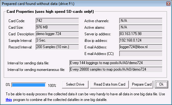
Prepare Card enables you to make a memory card (TRANSCEND
max 2GB) ready for use
with an iBOX.
"Prepare Card" clears all data
on that card and creates a file with default name
iBOX-EKO21.DAT
The size of this file is equal to the size of the formatted card.
After preparing a card it can be inserted into the iBOX
and a measuring period will start.
Before a card can be prepared
it needs (usually) not to be formatted.
The parameters (which are defined in the other menu parts
like Change Parameters) are written at the card, like:
- The Identification Text identifies a specific measurement location or period
- Sample interval (determines how often a sample is taken)
- Record Interval determines after how many samples data should
be written to card
(with average value and optional min/max/standard
deviation)
Notes: (there are some important notes, please read these carefully)
Downloading data through a SD card
reader is
the fastest way of downloading possible.
Press the Start button to start
downloading. Select a directoy where the data should be saved.
The progress
bar indicates the progress of downloading. After downloading the
program asks you if you want to prepare the card.
The data file name format is: date time.log, e.g.: ascii datafile on the server:
i052-20160104144600.txt
So in
this case the file is made 4 january 2016 at 14h46, from ibox NUMBER 052
In this menu can be set:
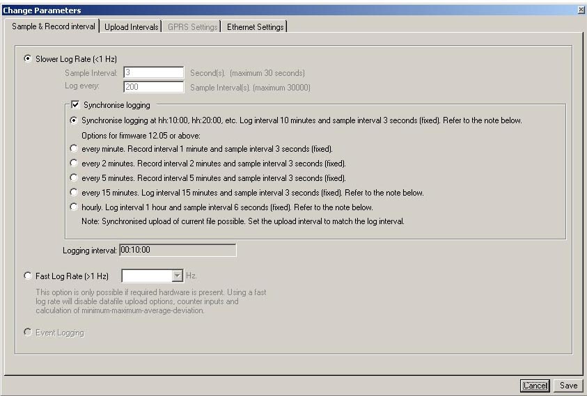
NOTE: fast logging only with special versions (only logging to SD Card and Ethernet is NOT active!)
> When synchronised logging is activated it will take 2 record intervals for
pulse counters to synchonise!
The first value after startup will be a zero in this case. So when
a zero value appears, it may indicate
that the system is restarted, probably by interruption of the power supply
(or re-inserted SD card).
For cumulative - non volatile counters the correct (cumulative) value will be
updated
and will even continue counting during the interruption of the
power supply !!
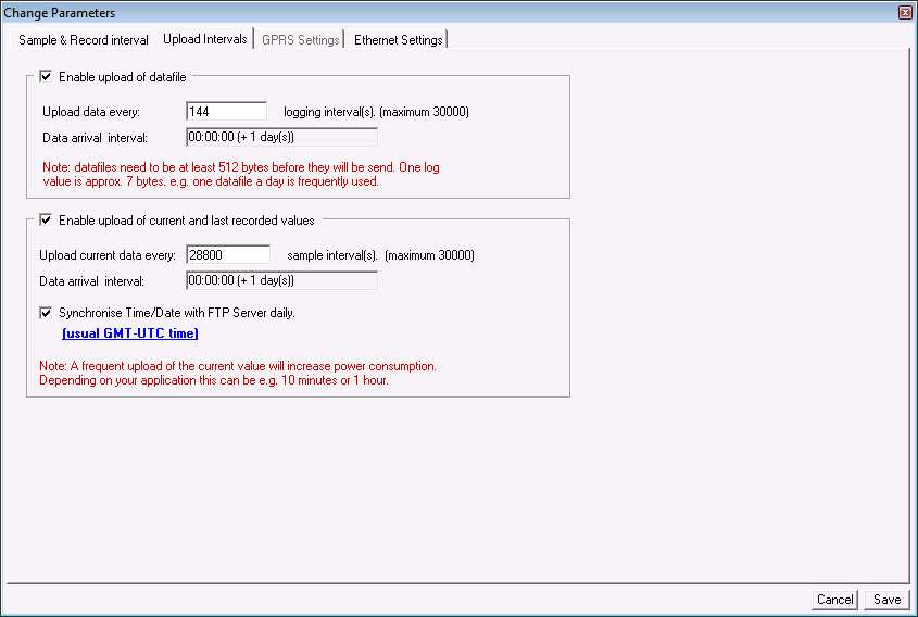
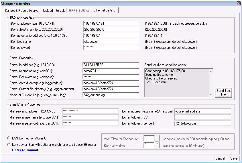
Choose menu: Change parameters - Upload interval
Upload current values: enter after how many samples current
values must be send to the server
(is used for making graphs and reading instantaneous values)
When upload of current values is active ALSO the UTC time synchronisation can be
set
(when current values are not frequently required set this eg once a day).
Upload Data files : enter after how many records
the data
file will be uploaded to a server
The data file name format is: date
time.log, e.g.: ascii datafile on the server: i052-20160104144600.txt
So in
this case the file is made 4 january 2016 at 14h46, from ibox NUMBER 052 .
DO NOT SELECT VERY SHORT INTERVALS
As the data is send in blocks of 512 bytes very short intervals are not
possible.
The settings should be so the datafile for upload is at
least 512 bytes!
Calculation of used memory:
Each character has one byte ; (;=delimiter for separation of colums for eg
import in Excel)
date ; time
; value1; value2 ; etc
Example of one line with data:
12-03-09;12:26:25;32.25 ; 4.03 has 28 bytes ,
so in this
case at least 20 log intervals must be entered in the upload setting
A practical tool for combining of downloaded files to one file is available, see manual here
Notes:
- when (default) email settings are entered an active alarm can be send via
email
- When used in low power mode, the connected router is only
switched on during data transfer
It will take some time until the connection is made, so
a wait time is required, which depends on the
type of network and provider..
You can check the
Wait time for your connection (for 4G router) by connecting it to a PC and
wait until internet connection is available. Add some seconds extra
for security.
The Keep alive time is the time the connetion will be
available after data transfer, eg for contacting the
webserver remote (eg for reading values/setting
parameters). When used with 4G router the sim card must
have a static external ip number for reaching the webserver. This is not
required for sending data only.
- You can check the upload to the server in advance by uploading a
testfile
- e-mail alarms are only possible when the e-mail server is from the
same provider as the network
ask EKOPOWER for supporting providers.
- The default ip address of the
iBOX is usual 192.168.0.200 and can be connected to a LAN network
eg with router ip address (gateway) 192.168.0.1 (must be in the same range as the
datalogger)
The iBOX has a static adjustable ip address (no DHCP for easy
port forwarding)
When more iBOX-2S systems are used with the same
configuration (eg nr 705) each system can be configured with
its own specific parameters , like Server iP address,
Filename , Server folder (directory) and logger identification txt
In this way the unique properties of each logger are easy to
recognize in the server.
This can be carried out by using an unique
configuration file, which can be modified by the user for each system with
the
same configuration file nr.
The uSD Card can be programmed with these parameters, and the
iBOX-2S will operate according to these settings.
The specific configuration file can be stored for backup in a
specific folder for each system and copied back to the
software folder when
required.
When a (wireless) Router (or WiFi Bridge) is used for ultra low
power application at remote site you can adjust
(in advance) some parameters:
> Wait time is the time the system wait for a respons from the
network
> Keep alive time is the time the system is available for contact,
see also the notes below:
NOTE: when the iBOX is supplied in ultra low power mode
you can make only direct contact with the iBOX
when you connect
the Ethernet cable first to the (at least one minute
unpowered) iBOX and then connect the power supply to the iBOX !
Low power mode is enabled again after you disconnect and connect the power of
the iBOX again and carried out without
Ethernet cable connected OR automatically 5 minites after power up.
NOTE:
When an iBOX is configured to send data files to a server and the internet
connection is
(temporary) not available, the collected data collection will continue and
all (not send data) will be send
when the internet
connection is
active again.
When a long period no internet connection is availble the datafile
can grow very big!
Be aware of that, especially when connected via 4G Router and powered via
battery
So do not operate a battery powered logger without an internet connection
if data file upload is selected!!
It may take a very long time to send the data afterwards, depending on speed
an size of data file!
This is NO problem when only the current value file is send to the server !
The iBOX system is supplied programmed ready for use and
the settings are usually entered (by Ekopower)
in the control
software
for test purposes .
We recommend
that you save the original configuration file separately for backup.
You have to change the preset server settings for your own
server!
NOTES:
> HOW to find the iP address of a server?
Start - execute - cmd<enter> (command mode)
enter command:
Ping www.servername.com<enter>
> HOW to find the MAC address of an iBOX?
At first make contact with iBOX webserver (type the ip address in browser)
Start - execute - cmd<enter> (command mode)
enter command: arp -a <enter>
The MAC address is shown now (at the line of the ip address of the iBOX)
eg:ip nr 192.168.0.200 and MAC address: 00-50-C4-28-10-81
and will always start with: 00-50-C4
The embedded WEBSERVER
Some parameters are also adjustable using the embedded webserver of the
iBOX.
How to make contact with the webserver of the iBOX?
This is possble in 3 ways:
1 LOCAL Connection
By using a cross cable and set the ip address of the PC according
the range of the iBOX
eg iBOX ip adress default 192.168.0.200 and choose ip address of
the PC eg 192.168.0.100
by choosing internet protocol (ip address not automatic but static
with sub net mask 255.255.255.0)
Type in your browser the ip address of the logger (default
102.168.0.200) type the username and password
(both defaut 2 times ekopower) and the webserver will appear, see
below
2 LAN (or WLAN, WiFi) Connection
Connect the iBOX (defaut ip address 192.168.0.200) with a router
with ip address in the range of the
iBOX eg 192.168.0.1 (gateway address)
Type in your browser the ip address of the logger (default
102.168.0.200) type the username and password
(both defaut 2 times ekopower) and the webserver will appear, see
below
3 WAN Connection remote over internet
Prepare the router at the iBOX end with portforwarding from outside
via port 80 to the ip address of the iBOX
(default 192.168.0.200). See the manual of your router.
Find the external ip address of this router at the iBOX end
eg 123.23.45.56 You can use a seach engine for
finding the extenal ip address
Type in your browser the extrenal ip address http: //123.23.45.56
type the username and password
(both defaut 2 times ekopower) and the webserver will appear, see below

See also:
Help
embedded
webserver v12
Demo embedded webserver
NOTE: the webserver is not accessible during a FTP session
(during sending a file to server)
In some cases you need to restart the browser and or repower the iBOX system
when the webserver
is not available.
Overview important logger parameters and possibilities how to set or change:
- via SD card by using the Control software and to prepare the card
- via the embedded webserver of the iBOX or iSENSE (iSENSE without
logging function to SD card)
| logger pararameter: | iBOX / iBOX-2S iSENSE with embedded webserver |
| time and date 1) | via webserver and via SD Card (UTC setting) |
| sample interval | via webserver and via SD card |
| record interval | via webserver and via SD card |
| upload interval | via webserver and via SD card |
| ip address/map server/etc. | via SD card |
| ip address of system | via SD card note: default ip address without SD card is 192.168.1.200 |
| set input type and nr 2) | via SD card |
| ranges and units 2) | via SD card |
| sample/record delay 2) | via SD card |
| set alarm conditions 2) 4) | via SD card |
| sms alarm message 4) | (via forwarded email) |
| email alarm message 4) | via SD card |
| description of logger | via SD card |
| UTC time synchronisation | via SD card |
| Log synchronisation (eg13:10, 13:20) | via SD card |
| FTP and server settings | via SD card |
| IP nr settings of logger | via SD card |
| timer switch settings & low power mode 4) |
via SD card (switching GPRS/4G router) |
| operation & actions | |
| controlling outputs 4) | via webserver (also over internet!) |
| clear card | via webserver and via SD card |
| read values and status | via webserver
and via optional online webdisplay / graphs |
| upload data to server 3) | via FTP
(automatically) via SD card transfer of data to PC |
| NOTES |
Two way
communication: 1 Data to server (via FTP) 2 Webserver (via LAN or via internet) The webserver is also remote available via internet using wireless GPRS/4G router and sim card has fixed ip nr See demo webserver here |
1) by setting time and date the system will restart, in
this way it is possible to set a start time (eg 12:00)
for synchronisation. Also the upload time can be changed in
this way.
2) password protected
3) a practical tool for combining of downloaded files to one file is
available, see manual here
Note: do not include incomplete
uploaded files in the file combine utility
as (after the data is resend) this will prevent double
values in the combined file.
So at first inspect the datafiles before using the file
combine function!
4) some mentioned features may not yet be available as each
system is supplied according your specifications
This is another useful tool for checking the operation of
the iBOX via webserver!
The instantaneous value of every active channel is displayed in
the first column and is updated every sample interval.
The last recorded values are displayed in the other columns. The
last recorded values are updated every record interval.
Use this option to enter parameters
After setting the time/date the iBOX resets but data
remains on the card.
If you reset the time the system will restart (for
synchronisation purposes eg start at 12:00)
Control
If hardware is implemented up to 3 switches can be operated via your
browser.
The state of the switch is displayed in the Status menu.
The switch has an open collector output and can be expanded with a power relay
(220V/6A)

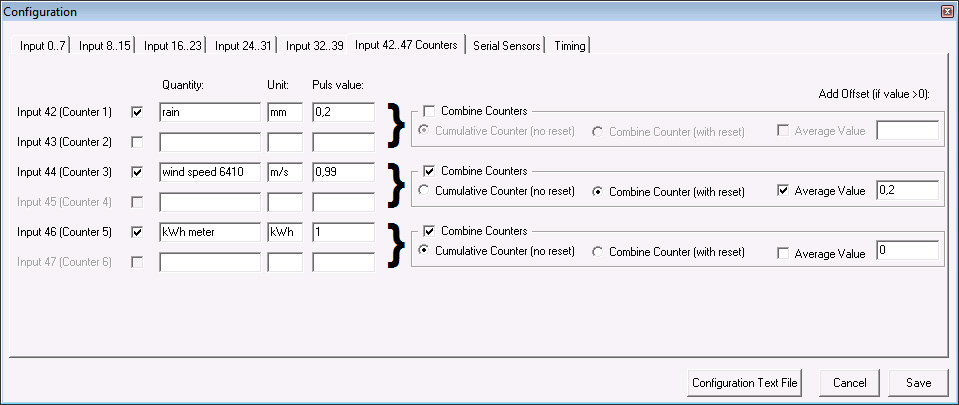
Select the input channels activated on your Logger. Note: A
selected channel has a fixed Input Type.
After you have selected a channel, you can fill in a Quantity
and a Unit (for example Quantity=Temperature and Unit=C).
Select a Minimum, Maximum, Average, Deviation or a Log sample.
Note: If Log sample is selected then all other options will be
disabled.
The defined alarm via e-mail can be set or changed in each channel.
Afterwards the memory card needs to be prepared
(all new parameters
are saved on the card and the logger read this data at start-up).
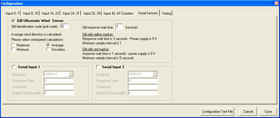
Serial sensors are only possible when pollng is possible, like with the acoustic ultrasonic anemometer.
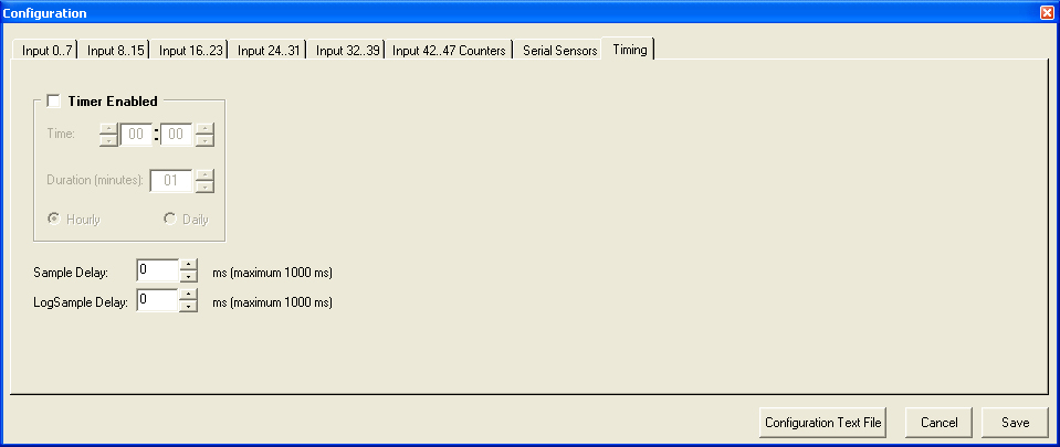
Two modes of sampling and recording are possible:
- sampling during record interval for recording average values
- just taking one sample and record (logsample)
Alarms
Alarms can be specified: with several possibilities (higher/lower/between
an alarm value)
2 alarms with hardware output for switching are possible
and alarms for sending email alarm notifications (emails can be forwarded to sms
message ,
using a email/sms service!)
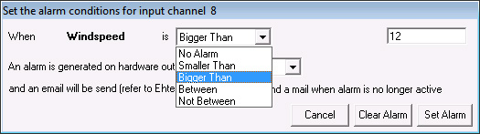
Choose the alarm condition : channel , condition, value (can also be average
value!)
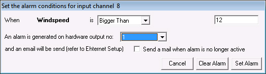
Choose the hardware alarm output (2 possible) , open collector or relay
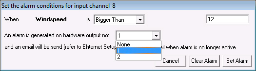
Also a notification via email can be send when the alarm is no longer active
> The webserver is not accessible during a FTP session
(during sending a file to server)
In some cases you need to restart the browser and or repower the iBOX system
when the webserver
is not available.
> Procedure for changing the anemometer calibration:
When a calibrated anemometer must be exchanged, the channel configuration
should be changed of that logger,
according to the anemometer calibration data.
Follow this procedure:
* download all old data from cards, using the original configuration
* choose Memory Card, logger configuration and enter the password (available
from your supplier)
* select in channel configuration the corresponding wind input channel
note that: the calibration curve of a linear anemometer is expressed by: (refer
to calibration certificate)
v = af + b v=wind speed (m/s), a=slope, f = frequency (Hz), b=offset
(m/s)
so in order to calibrate the datalogger according to the calibration data of
the anemometer:
- enter the new offset of the new anemometer (e.g. 0.365 m/s)
- enter new maximum of the range . The new range for a calibrated anemometer
is calculated via:
old range * new slope/old slope (eg new range = 50 * 0,76/ 0,77
(50 is old
range, 0,76 is new slope, 0,77 is old slope)
* save the new configuration
* put the memory card of the logger in the SD Card slot of the PC
* prepare the card with the new configuration and put the memory card in the
logger again
> Uploading data files
* when an uploaded file to the server could not be completed, the complete
file willl be resend
during the next session and the incomplete file will stay at the server
* when it is - temporary- not possible to send a data file to the server, the
data is stored
at the SD card and will be send when it is possible again.
* Reasons for not successful uploads can be: bad or no internet connection, no
cover
of 4G in case of use of a 4G router , server not available etc.
- Some hints and tips in order to solve
problems with upload of data
1. Check server settings and send testfile to server, check the arrival on the
server
2. Check datafile will be >512 bytes (upload data file for at least 12 loggings
in this case)
3. Check power supply (battery) Lithium battery must be appr 7.2 volt
When external power supply is used it must be at least 6 volt
4. Connect battery direct to 4G Router and check after how many seconds the NET
led is coming up
(see also enclosed details for 4G Router R700)
This time is depending on provider and network conditions. (In the
Netherlands we use 75 sec )
(You may carry this out also with external power supply)
The adjusted wait time in the Ethernet settings (when Low power mode is
active!) must be at least
10-20 seconds more for security , see below
5 When mains power is available the external power supply can be used (eg 6V )
In this case the logger system can also operate in Full Power mode : choose
LAN connection always on
and prepare a Card for Full Power
Then logger AND 4G Router will be always ON, so always network connection and
no wait time required.
In this case the Router + line can also be connected to nr 11 (+ of power
supply)
6 Do not change the sample and record intervals as it is adjusted with the
lowest power consumption
for battery operation
7 Do not operate the system without functioning internet connection (datafile
will accumulate!!) ,
the datafile upload must be possible
If this has happened prepare the card again (and collected data will be
saved)
> Procedure for adjusting wind vane in software
The direction indication of the wind vane can be "fine tuned" in software.
Follow this procedure:
* download all old data from cards, using the original configuration
* choose Memory Card, logger configuration and enter the password (available
from your supplier)
* select in channel configuration the corresponding wind vane channel and enter
the required value
in the offset field. Eg when you want that the direction must indicate 11 degrees more enter
value 11.
Note that the offset value must always be a positive value, so when you
want to decrease the vane
reading with eg 9 degrees you should add (360-9)=351 degrees!
* save the new configuration
* put the memory card of the logger in the SD Card slot of the PC
* prepare the card with the new configuration and put the memory card in the
logger again
> After starting the program there is no Configuration file listed.
The program can not find any Configuration files in the directory
in which the program is installed.
Copy your Configuration file
into the directory in which the program is installed.
> Setup can not find an SD card drive.
If an SD card drive is installed at your computer select the right SD card drive
letter.
A SD Card drive can also realized via usb !
> No memory card in slot present error.
There is no memory card in the slot which is installed by the
setup option.
Put the memory card in the correct slot
and see which drive letter is active.
>After preparing the iBOX reacts with a "card not prepared"
error.
The card is probably not prepared.
Note that it is NOT required to format the card. If you fotmat the card
you must do this using FAT
(not FAT32)
and fast (without MS DOS starting up!)
HINTS
- a practical tool for combining of downloaded files to
one file is available, see manual here
Note: do not include incomplete uploaded files
in the file combine utility
as (after the data is resend) this will prevent "double values" in the
combined file.
So at first inspect the data files before using the file combine
function!
- if the system is not responding at all OR a LED is
constant ON :switch power off
and reconnect again for restart
(LEDS will be flashing and green LED wll flash during sampling only)
Tthe logger will also start again after taking out the SD card and re
insert the Card in the logger.
HARDWARE SPECIFICATIONS
DATALOGGER
FOR ANY
MONITORING PROJECT
Besides standard solutions we supply tailor-made systems for specialised
purposes
POSSIBILITIES of the iBOX (7-16 inputs) and iBOX-2S (1-6 inputs):
> Simple operation via
your web browser, also remote over the internet
>
Access remote sensors over the internet or via optional Wireless WAN connection
> Log
data from sensors, voltages, currents, pulses, status etc
> SD-card
memory for secure data storage or backup:
Secure Digital (SD) Memory Card:
128Mb
2 Gb (uSD for iBOX-2S)
> Instantaneous values automatically transferred to server or website with
optional Web dispay and online graphs
> Data files automatically transferred to your FTP server or Cloud (either via
ethernet or wireless 4G connection)
> Integral online status display via built-in webserver
> Optional Outputs can be controlled via the user-interface (via webserver)
> Optional
Alarms can trigger outputs and send email alarm messages (may be forwarded as
SMS text alerts)
> Web hosting optional available for demo & test purposes
> Measure & Control up to 3 switches
via internet, using your browser
> Built-in webserver for(partial) setup &
reading values & status and for (protected) setup & setting logger parameters)
> Quick and easy setup of the system (including setting logger parameters) by
using the
iBOX control software
>
For remote or mobile
applications an Ultra Low Power (ULP) version is availble with
optional ULP wireless (GPRS/4G) router
The new iBOX family of iP
dataloggers (4th generation) -with internet connectivity options-
it is possible to realize a telemetry & control system over the internet:
receive data files at your server,
control outputs via your browser, alarms can trigger outputs and receive
alarm notification via email etc.
For remote or mobile applications an Ultra Low Power (ULP) version is availble with optional wireless 4G router
DESCRIPTION of iBOX system
The iBOX is an
easy-to-use, accurate and reliable internet enabled datalogger system
with built-in
web server with versatile inputs :1 up to 16 analog & digital inputs , status,
pulsinput
The iBOX has integrated internet connectivity with Ethernet connector and
a SD memory card
(128Mbyte up to 2 Gbyte) for data storage.
Optional possibility: wireless 4G router for mobile or remote
applications in Wireless WAN.
It is an essential
tool for state of the art iP measurements for e.g. meteorology, environmental
monitoring, wind energy
feasibility studies, kWh metering, but also for general purpose projects:
complete systems according your
requirements can be supplied!
Controlling and working with the IBOX is made easy with the built-in webserver.
The iBOX logger configuration is pre-adjusted by EKOPOWER (number and type of
input channels) and the
logger parameters (like sample and record interval) are stored on the SD memory
card.
Besides the logger configuration also the recorded data is secure stored at the
SD card.
Moreover by using the software the setup of the system (including setting
additional parameters) can be carried
out quick and easy, like:
- ranges and units (password
protected, preset at factory: according to the physical inputs boards and
connected sensors/signals)
- optional alarms: software alarms via e-mail (or forwarded as SMS) and hardware
alarms:
open collector output (with optional DIN rail relais)
- sample interval, record interval, upload interval etc.
- iP address for server, iP address of iBOX itself etc.
- moreover up to 3 switches van be controlled via the webserver, also remote
over the internet (if implemented).
The iBOX can send automatically data files via FTP to a specified
server( e.g. the server of your website)
at pre-adjusted intervals:
- file with instantaneous status and values
- file with recorded values (eg average values with optional min/max/standard
deviation during each record interval)
The online graphs can
be created via:
- our server and copied into your own website/application (simply link, using
copy and paste the graph)
- our server for historical graphs
APPLICATIONS:
measurement (industrial and remote field applications) e.g.:
* monitoring of
machines * energy managemen (kWh metering) * renewable
energy projects
* meteorology *
research
* environmental technology
* process monitoring * feasibility
studies * water
level
monitoring
* building physics * solar energy projects
(PV metering) * wind energy evaluation
|
|
(each system will be supplied according to customer specifications: ask for availability !) |
|
|||||||||||||||||
|
Features |
|
|
iBOX /iBOX-2S system |
|
|
|
|
|
|
||||||||||
|
MEMORY |
|
|
|
|
|
|
|
|
|
|
|||||||||
|
memory card |
|
|
Secure Digital (SD) or uSD for iBOX-2S |
|
|
|
|
||||||||||||
|
memory size |
|
|
Standard 128MB |
|
|
|
|
|
|
||||||||||
|
Data file format |
|
|
ASCII (direct import in Excel) |
|
|
|
|
||||||||||||
|
INPUTS |
Optional wireless |
|
|
|
|
|
|
|
|
|
|||||||||
|
Analog inputs (or status) |
|
1 up to 16 standard or special*) inputs in one unit iBOX-2S up to 6 inputs |
|
|
|
|
|||||||||||||
|
Expansion units |
|
|
total max 16 |
|
|
|
|
||||||||||||
|
RESOLUTION |
|
|
Analog: iBOX-2S standard 12 bits ADC |
|
|
|
|
||||||||||||
|
Counter inputs |
|
|
Option: up to 6 (12bits) or up to 3 pc 24 bits non-volatile counter |
|
|
|
|
|
|||||||||||
|
SAMPLE INTERVAL |
|
Adjustable 1 - 200 sec |
|
|
|
|
|||||||||||||
|
OUTPUTS |
|
|
|
|
|
|
|
|
|
|
|||||||||
|
Alarm outputs Control outputs |
|
|
up to 2 open collector (2 email/sms) up to 3 open collector |
Optional power relais at DIN rail |
|
|
|
|
|
||||||||||
|
e-mail alarm |
|
|
Option |
|
|
|
|
||||||||||||
|
ETHERNET/INTERNET |
|
Optional WiFi wireless Bridge or |
|
|
|
|
|
|
|||||||||||
|
Web server |
|
|
Embedded |
|
|
|
|
|
|
||||||||||
|
POWER 1) |
|
|
|
|
|
|
|
|
|
|
|||||||||
|
Standard version ultra low power-field version |
|
6-12 Volt DC via 220V adaptor Option with Battery / solar module |
Or 24 V DC |
|
|
|
|
|
|||||||||||
|
Internal excitation for 4..20 mA |
|
Option |
|
|
|
|
|
|
|||||||||||
|
Backup battery |
|
|
Option (for logger part rechargeable) |
|
|
|
|
||||||||||||
|
*) standard inputs: 0/4..20 mA, voltage inputs, temperature inputs, special inputs for all kinds of sensors and signals (also mV inputs) on request |
|||||||||||||||||||
|
TEMPERATURE RANGE -25
to +70 C (industrial / field version) |
|||||||||||||||||||
|
1)
For remote applications: an ultra low power system with battery life up to
10 years, running on one battery pack |
|||||||||||||||||||
EKOPOWER reserves the right to change specifications and functions
without prior notice,
for improvement of the system
Supplied by EKOPOWER - The
Netherlands with
Metaalunie
conditions,
Warranty: 2 years (carry-in) based on normal operational conditions;
damage by chemical environments and lightning is excluded from warranty.
Place logger in heated cabinet in (very) cold climates.
Take care for lightning arrestor and proper grounding of the
lightning sensitive signals, like anemometer etc
When used outside place the logger in well closed waterproof box with
silicagel bag.
Designed and made in the EU (The Netherlands).