www.ekopower.nl version 7.0 august 2009
SOFTWARE MANUAL
EKO21N control software
Refer to the hardware manuals for EKO21N
Refer to the datasheets for EKO21N
Refer to webpage of EKO21
Introduction
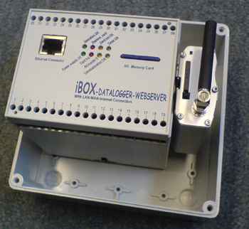
The EKO21N dataloggers are new (state-of-the-art)
and very compact, easy to use and flexible.
The EKO21N ("stand alone" low power datalogger) has a serial connector (RS232 with
optional USB cable)
and has ultra low power consumption (up to 10 years operation with one battery
pack,
ideal for remote applications if no communication is required)
The EKO21N-iP has a wireless GPRS internet connection
and can send datafiles wireless (via internet) to a server
(one way remote communication) , ideal for remote or mobile applications with
optional SMS alarm messages
and
online
graphs and
webdisplay
All systems can be used for a wide range of monitoring applications
for eg:
nature & technology, energy & environment, laboratory
& industry
and for wind, weather and meteorology.
The EKO21N systems are easy to use, accurate and reliable
datalogger system essential for e.g.
besides general purposes,
wind energy feasibility studies, meteorology, weather stations,
energy and environment.
Controling and working
with the EKO21N is made easy with this Control Program
for Windows.
For best possible performance of
the system as a whole read this manual carefully before using
the system.
When installing the software take note of the Tips!
If
you need to go into the field take this manual with you in order
to solve possible problems.
All the text printed
Italic are buttons or menu options which can be used in the program.
Text printed underlined are important notes and tips.
Notes before starting:
Use a computer with
serial RS 232 port (or USB port with Serial Cable) and a
SD Card drive for reading the memory cards.
Most PC's (or notebook) has a SD card drive or USB port.
Any computer can be equiped with an external
SD Card Memory drive (available from your supplier),
which can be connected to the USB port. This equipment is also
available from your local computer supplier.
Note that the SD Card Memory card is a (solid state) harddisk.
Windows will install this card as a hard disk!
After
you inserted a SD Card memory card into the slot Windows should
add a drive letter on your computer.
The added drive letter should be selected in the setup of the
iBOX-EKO21N Control software.
How to get started?
Installing the EKO21N Control Software
Installing the Control Software on a Windows 95/98/2000/NT/XP
based PC.
The software setup program (in a zip file) will
either be mailed to you or put on an extra SD Card.
Copy the zip file
in a directory on your computer. Unzip the file and run the setup.exe file.
The
Install Wizard will guide you through the installation process.
Tip: When the Install Wizard prompts you for a destination directory
in which to install the software
change its name into a shorter and easier to use directory name
by pressing the change Directory button
e.g. C:\iBOX-EKO21N (C:\ or D:\ depends on the hard drive you
want to use).
After installing
the Control Software you have to copy the supplied Configuration file into the
same folder in which the Control Software is installed.
This configuration
file comes together with the software and will be mailed to you or put on an
extra SD Card. The configuration file name is formatted as follows:
- Configuration-E.003 for an iBOX (E
for Ethernet) with logger identification code 3.
-
Configuration-G.009 for an EKO21N-iP (G for GPRS+RS232 interface)
with logger identification code 9.
Using the Control Software for the first time
After installing the program you can start using the program.
Press the START button and choose PROGRAMS. Select
the iBOX-EKO21N program and start the program.
(Refer to the Windows Help about making a shortcut to the Desktop)
Select the supplied Configuration file see below and enter.
The SD Card drive should be specified when
the memory card menu is choosen
First put in a SD card in the slot or SD reader and Windows
will recognize the drive letter.
Select the card drive letter which is indicated by Windows.
The serial port nr should be selected when serial connection is
made (usual port nr 1).

Logger Description
You can give a description of your iBOX or EKO21N. You can enter
eg the project name or location of the system.
Your system is now ready to work with the iBOX or EKO21N Datalogger.
With the Control Software you are able to control and manage wind
measurement projects in a fast, easy and reliable way
Note: For EKO21N-iP the GPRS module needs to be
programmed before use, see the hardware manual of the EKO21N
Using the EKO21N Control Software
Basic operations
Every time you use the iBOX-EKO21N Control Software
the last used configuration file is opened automatically.
If you want to use
a different Configuration File of a particular iBOX or EKO21N select it from the
drop-down list box.
> Menu Memory Card
All options available in the Memory Cards menu interact with
the SD memory card, which should be in the SD slot
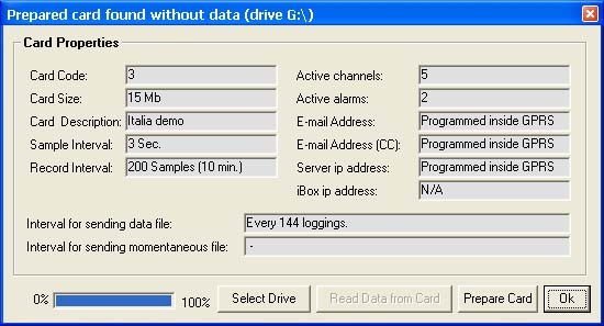
Prepare Card
Prepare Card enables you to make a memory card ready for use
with an EKO21N. "Prepare Card" clears all data
on that card and creates a file with default name
iBOX-EKO21.DAT
The size of this file is equal to the size of the formatted card.
After preparing a card it can be inserted into the
EKO21N
and a measuring period will start.
Before a card can be prepared
it needs to be formatted using Windows and may not contain any
files! The parameters (which are defined in the other menu parts
like Change Parameters) are written at the card, like:
- The Identification Text identifies a specific measurement location or period
- Sample interval (determines how often a sample is taken)
- Record Interval determines after how many samples data should
be written to card (with average value and optional min/max/standard
deviation)
Notes: (there are some important notes, please read these carefully)
- If there is data (which is not downloaded) on the card before
preparing it the program will respond with a warning and will
download the data from the card into a selectable directory. After downloading
all data will be erased and the card will be prepared.
The card is now ready for use in the EKO21N.
- If a card is prepared for use in logger 1 (with Logger Code
1) and inserted in logger 2 (with LoggerCode 2) it will respond
with the error message "Card not Prepared"
(on LEDS and through the Status option).
Download possible present
data using the Configuration file belonging to logger 1 and prepare
the card using Configuration file belonging to logger 2.
Insert card into logger 2 and logging will start.
- You may delete the iBOX-EKO21N.DAT file on the card if you
want to use it for other logger configuration (save data first:
download card for all data will be erased!) After erasing the SD card can be prepared again.
Read Data from Card (Download Data from
SD card)
Downloading data through a SD card reader (either via SD reader
via USB or SD drive of laptop) is
the fastest way of downloading possible. Press the Start button to start
downloading. Select a directoy where the data should be saved.
The progress
bar indicates the progress of downloading. After downloading the
program asks you if you want to prepare the card.
Change Parameters at SD card
It is possible to change the Measurement
Parameters (and Configuration data) by preparing the memory card
again.
Parameters included are Identification Text which identifies a
specific measurement period, Sample and Record Interval and Timing
Method etc.
Overview important logger parameters and possibilities how to set or change:
- via SD card means using the Control software and to prepare the card
- via the embedded webserver of the iBOX or iSENSE (iSENSE without
logging function to SD card)
>>>see
Help
embedded
webserver
>>>see
Demo embedded webserver
| logger pararameter: |
EKO21N
with serial interface |
EKO21N-iP
with
GPRS modem |
| time and date 1) |
via RS232/USB |
via RS232/USB |
| sample interval |
via RS232/USB
and via SD card |
via RS232/USB or
via SD card |
| record interval |
via RS232/USB
and via SD card |
via RS232/USB or
via SD card |
| upload interval |
- |
via SD card
|
| ip address/map server/etc. |
- |
via SD card |
| ip address of system |
- |
- |
| set input type and nr
2) |
via SD card
|
via SD card
|
| ranges and units 2) |
via SC card |
via SD card |
| sample/record delay 2) |
via SD card
|
via SD card
|
| set alarm conditions
2) 4) |
via SD card |
via SD card |
| sms alarm message 4) |
- |
via SD card |
| email alarm message 4) |
- |
(via forwarded
sms) |
| description of logger |
via RS232/USB
and via SD |
via RS232/USB
and via SD card |
timer switch settings
& low power mode 4) |
- |
via SD card (for
switching modem) |
| operation & actions |
|
|
| controlling outputs 4) |
via RS232/USB
|
via RS232/USB |
| clear card |
via SD card |
via SD card |
| read values and status |
via RS232/USB
|
via RS232/USB
and via
optional online
webdisplay /
graphs |
| download data 3) |
via RS232/USB
and via SD |
via FTP (automatically)
or
via SD card |
NOTES
|
Stand alone system
communication is possible via:
- RS232 or USB to PC/laptop
- exchange SD card
|
One way (remote)
communication:
The system sends files only via
wireless GPRS connetion to server
via internet
Local RS232/USB contact to PC |
1) by setting time and date the system will restart, in
this way it is possible to set a start time (eg 12:00)
for synchronisation. Also the upload time can be changed in
this way.
2) password protected
3) a practical tool for combining of downloaded files to one file is
available, see manual here
4) some mentioned features may not yet be available as each
system is supplied according your specifications
> Menu Serial Communication
After connecting the supplied serial cable it is possible to
make contact with the logger through your serial communication
port.
When connected correctly the "RS232=ON" LED will light
up.
Note: When a PC is connected to the logger through a serial communications
port the logger consumes more power.
If you do not use this connection please remove the serial cable.
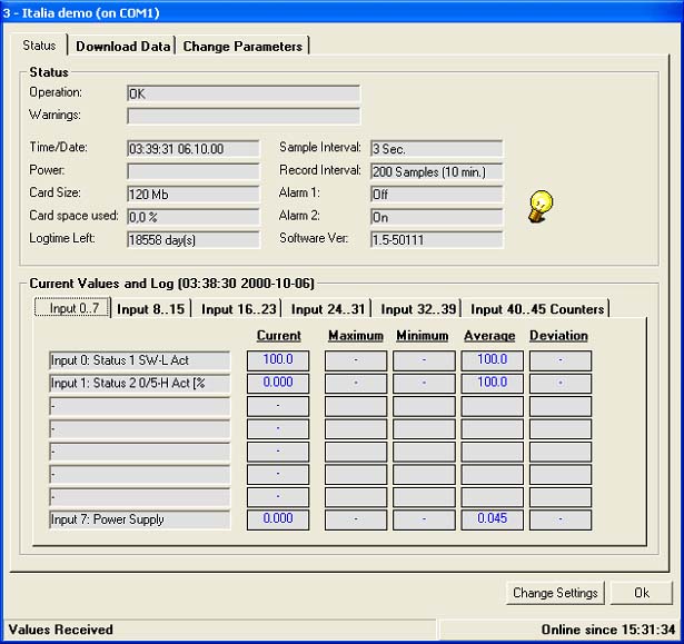
Status and current values
With this option it is possible to check the operation of
the logger, see below (iBOX via wenbserver)
If the operation is not ok the type of error is given here e.g.
a full card, low power, etc.
Besides checking for errors it is also a good tool for viewing
the settings e.g. sample and record interval, number of input
channels, etc.
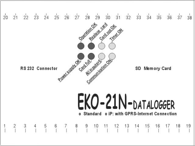
he status is also displayed at the iBOX or EKO21 with LEDS, see
below.
Nomally the green LEDS Operation OK and Power supply OK are flashing
during each sample.
When card is not OK it may also be that a card with wrong
code is entered
Current Values
This is another useful tool for checking the operation of the
EKO21N (iBOX via webserver!).
The instantaneous value of every active channel is displayed in
the first column and is updated every sample interval.
The last recorded values are displayed in the other columns. The
last recorded values are updated every record interval.
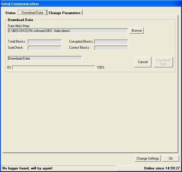
Download Data via serial connection
Downloading data through serial port is much slower than downloading
through PC card drive and consumes much more power!
Note: With every logging that is sent by the EKO21N a sumcheck
is sent with it. If the sumcheck made by the EKO21N differs
from the sumcheck made by the PC an error is generated. That particular
logging is sent again until no errors are detected.
When 25 errors are received downloading is stopped! Usually these
errors occur because of a bad (telephone) connection.
Try downloading a few hours later, if the problem persists check
your modem or contact your telephone company.
After downloading check the data for errors. If everything looks
allright you can clear the card or continue without clearing.
When you clear the card the program asks you if you want to change
sample or record interval.
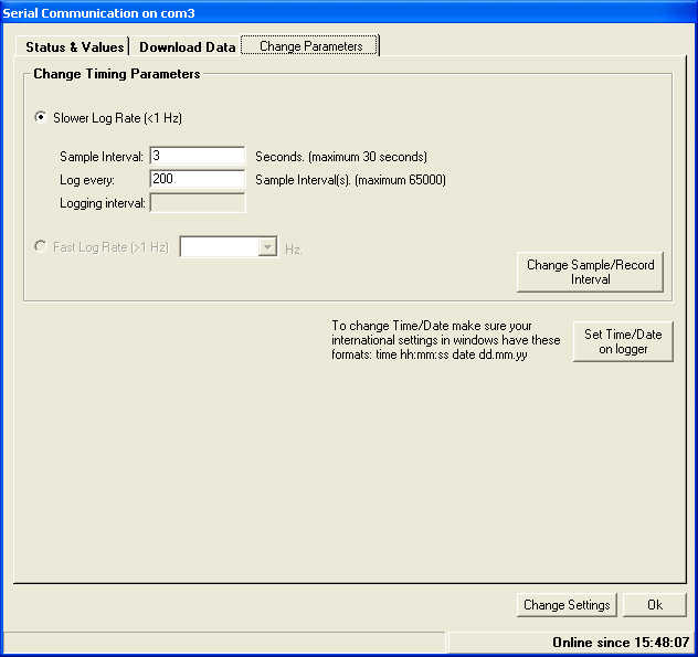
Change Logger Parameters via
serial connection
Use this option to copy the local time/date to the time/date
on the logger. Before changing the time make sure the local time
(on your PC) is correct (refer to Windows Help on setting time/date
on your PC). After setting the time/date the iBOX resets but data
remains on the card.
It is possible to change the sample and record interval without
preparing the memory card. After changing these parameters data
which was already on the memory card will NOT be lost. Notes:
- if you reset the time the system will restart (for
synchronisation and start eg at 12:00)
Change Settings:
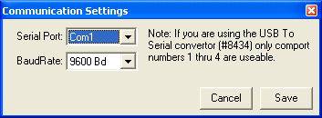
You can change serial port setttings
When using a EKO21N with RS232 and a modem, you can make a
dial-in connection.
First fill in an telephone number and press Save. Then click on
Serial Communications.
When the dialing is finished, you can see the status and current
values of the datalogger
> Menu Change Parameters
(prepare card afterwards
to make changes effective!)
In this menu can be set:
- sample and record intervals (for all models iBOX and EKO21N)
- internet upload intervals (only for iBOX and EKO21N-iP)
- GPRS settings (only for EKO21N-iP)
- ethernet settings (only for iBOX)
- serial settings (only for EKO21N or EKO21N-iP, GPRS modem
disconnected)
Sample & Record interval (for all models iBOX and EKO21N)
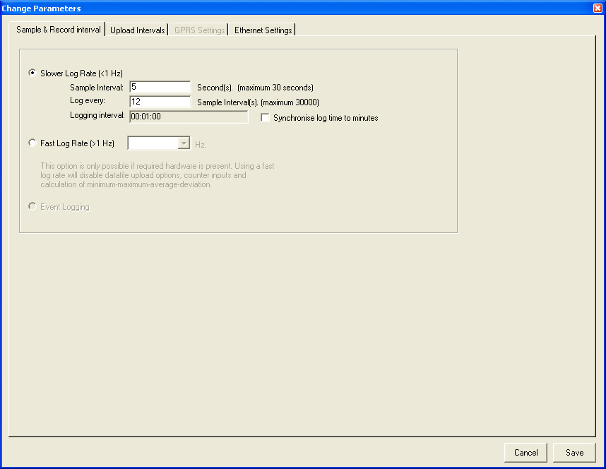
The sample interval can be changed with menu: Change parameters-
Sample & record interval and prepare card again .There are
some important notes, please read these carefully: If there is
data (which is not downloaded) on the card before preparing it
the program will respond with a warning and will NOT prepare the
card. Download the data from the card first (check if data is
correct!) and try preparing it again. The program will erase all
data on the card and prepare it. The card is now ready for use
in the EKO21N.
If a card is prepared for use in logger 1 (with Logger Code
1) and inserted in logger 2 (with LoggerCode 2) it will respond
with the error message "Card not Prepared" (on LEDS
and through the Status option). Download possible present data
using the Configuration file belonging to logger 1 and prepare
the card using Configuration file belonging to logger 2. Insert
card into logger 2 and logging will start.
Upload intervals (Only EKO21N-iP with GPRS modem)
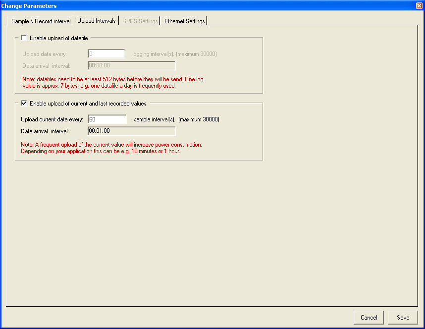
Choose menu: Change parameters - Upload interval
Upload data/current every: fill in after how many samples data/current
values must be send.
Data arrival interval: after how many minutes/hours a data/current
file will be uploaded to a server.
Note: when changing upload intervals, data arrival interval will
automatically be changed to.
DO NOT SELECT VERY SHORT INTERVALS
As the data is send in blocks of 512 bytes very short intervals are not possible.
A practical tool for combining of downloaded files to
one file is available, see manual here
Calculation of used memory:
Each character has one byte ; (;=delimiter for separation of colums for eg
import in Excel)
date ; time
; value1; value2 ; etc
Example of one line with data:
12-03-09;12:26:25;32.25 ; 4.03 has 28 bytes
Note: The data of the datalogger EKO21N-iP can send -for testing
& evaluation purposes- to a directory
of one of our servers.
GPRS Settings (Only EKO21N-iP : GPRS version) >>>
see also additional instructions in hardware manual!
The EKO21N-iP system is supplied with programmed ready for
use GPRS modem.
The GPRS settings are entered (by Ekopower) in the control software
according to the received SIM card (if available).
Also the password in the EKO21 control software for internet operation
is entered.
Also the server settings are default entered for the www.ekopower.net
test website and saved in the configuration file.
We recommend that you save this file separately for backup. You
need to enter your own server data (you may use the server of
your website).
The GPRS modems is usulally already programmed in advance and
loaded with the communication parameters in memory registers,
like server, passwords, data GPRS provider, but not in all cases:
some customers wnat to do it themselves or modify it.
To change the present GPRS settings follow this procedure carefully!
To enable the GPRS modem for sending data using your own FTP server
it needs to know different things like: (refer to picture below)
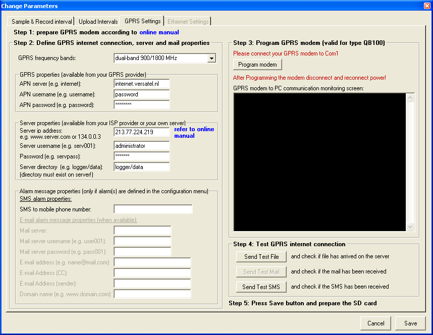
At first prepare the GPRS modem, see also the hardware manual
of the EKO21N part A12
- Put a sim card in the slot of the GPRS modem: GPRS data card,
with de-activated pin code (you can do that with a mobile
phone)
- Connect GPRS modem to PC using the supplied serial cable with
GPRS adaptor
- Connect this cable to the pc-com port (selected in the setup)
and the GPRS modem and connect power to GPRS unit
(apply voltage between 6 and 15V Volt, red =+!)
APN server and login properties (APN setting are provided
by the GPRS network provider).
Note that a sim card without pin code must be used in the
GPRS modem
You can disable the pin code of a sim card by putting the sim
card in a mobile telephone.
If international contact is required ask the GPRS provider to
activate roaming
For the destination FTP server is default entered the ekopower.net
server for testing purposes.
Note: you can change this server, eg use your own website: you
can use the www.yoursite.com data!
Do not forget to make a directory in advance!
You have to change the preset FTP settings for your own server!
After entering all the required settings, press save and after
that the modem can be programmed using the ”Initialize modem”
button.
After succesful programming of the GPRS modem disconnect power
from modem and reconnect again ("cold start").
Then try to send a testfile by pressing the “Send Test File”
button.
Then check the testfile is received at the server, using your
FTP program.
If email or SMS alarm is implemented do the same .
Note that some email providers require password for sending mail!
> Menu Change Configuration
The logger configuration can only be changed by autorized
users: password is available upon request.
In this menu can be set:
- ranges and units (preset at factory: do not change as this
must be according to the physical inputs boards and connected
sensors/signals!!)
- alarms: software alarms via SMS (and/ or email using GPRS
modem) and hardware alarms: open collector output (if present
in hardware)
- timing variables (do not change)
- NEVER CHANGE THE NR AND TYPE OF INPUTS AS THE SOFTWARE CONFIGURATION
MUST MATCH WITH THE HARDWARE INPUTS & SENSOR
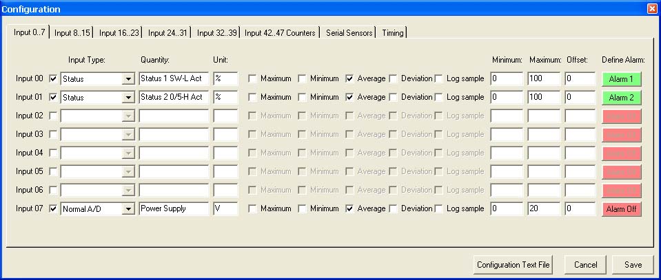
Inputs
Select the input channels activated on your Logger. Note: A
selected channel has a fixed Input Type.
After you have selected a channel, you can fill in a Quantity
and a Unit (for example Quantity=Temperature and Unit=C).
Select a Minimum, Maximum, Average, Deviation or a Log sample.
Note: If Log sample is selected then all other options will be
disabled.
The define alarm via SMS or e-mail can be set or changed by channel.
Afterwards the memory card needs to be prepared (all new parameters
are saved on the card and the logger read this data at start-up).
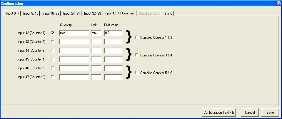
Counters
The counter value represents the
value of 1 count (e.g. 0.2 mm for rain collector or 0.5 Wh for kWh transducer.).
The range is standard 12 bits. Combined counter have a range up to 24 bits
(excluding optional pre-scaler).
Combined counters can be supplied also with battery backup, so a non-volatile
kWh meter can be created.
In order to reset this type of counter an extra hardware-reset switch can be
implemented.
Serial Sensors
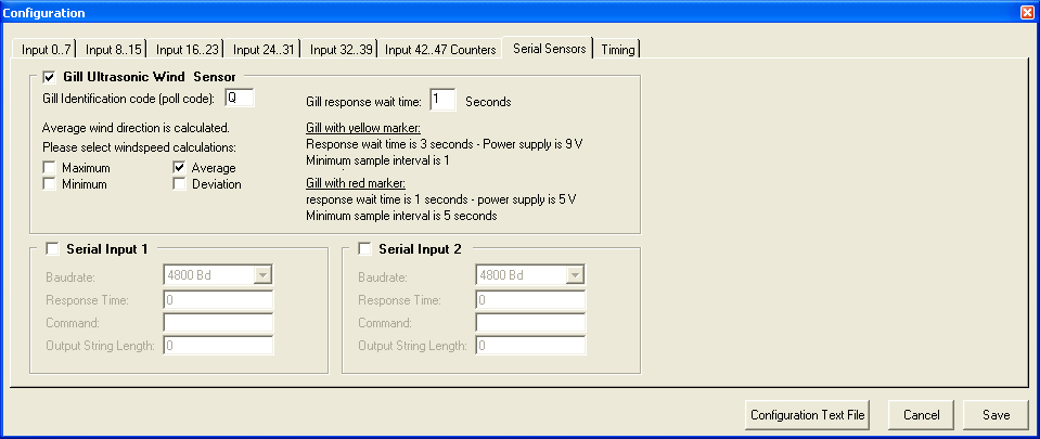
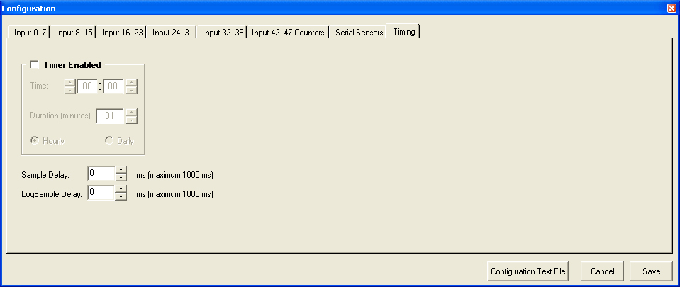
Timing
Alarms
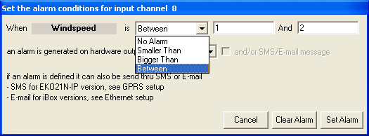
Alarms can be specified: with several possibilities (higher/lower/between
an alarm value)
2 alarms with hardware output for switching are possible
and alarms for sending sms/ email alarm notifications
Troubleshooting & Hints
> Procedure for changing the anemometer calibration:
When a calibrated anemometer must be exchanged, the channel configuration
should be changed of that logger, according to the anemometer calibration data.
Follow this procedure:
* download all old data from cards, using the original configuration
* choose Memory Card, logger configuration and enter the password (available
from your supplier)
* select in channel configuration the corresponding wind input channel
note that: the calibration curve of a linear anemometer is expressed by: (refer
to calibration certificate)
v = af + b v=wind speed (m/s), a=slope, f = frequency (Hz), b=offset
(m/s)
so in order to calibrate the datalogger according to the calibration data of
the anemometer:
- enter the new offset of the new anemometer (e.g. 0.365 m/s)
- enter new maximum of the range . The new range for a calibrated anemometer
is calculated via:
old range * new slope/old slope (eg new range = 50 * 0,76/ 0,77 (50 is old
range, 0,76 is new slope, 0,77 is old slope)
* save the new configuration
* put the memory card of the logger in the SD Card slot of the PC
* prepare the card with the new configuration and put the memory card in the
logger again
> Procedure for adjusting wind vane in software
The direction indication of the wind vane can be "fine tuned" in software.
Follow this procedure:
* download all old data from cards, using the original configuration
* choose Memory Card, logger configuration and enter the password (available
from your supplier)
* select in channel configuration the corresponding wind vane channel and enter
the required value in the offset field.
Eg when you want that the direction must indicate 11 degrees more enter
value 11.
Note that the offset value must always be a positive value, so when you
want to decrease the vane reading with eg 9 degrees
you should add (360-9)=351 degrees!
* save the new configuration
* put the memory card of the logger in the SD Card slot of the PC
* prepare the card with the new configuration and put the memory card in the
logger again
> After starting the program there is no Configuration file listed.
The program can not find any Configuration files in the directory
in which the program is installed.
Copy your Configuration file
into the directory in which the program is installed.
> Setup can not find an SD card drive.
If an SD card drive is installed at your computer select the right SD card drive
letter.
A SD Card drive can also realized via usb !
> There is no serial communication port selected.
There is no serial communication port selected. Select Change parameters and
then change settings.
You can check the active port nr in windows (see Contro Panel/System/Hardware/Device
Manager)
If you use an USB to serial converter adjust the port number between 1 and 4 if
possible.
> No memory card in slot present error.
There is no memory card in the slot which is installed by the
setup option.
Put the memory card in the correct slot
and see which drive letter is active.
>No logger found error.
Check if the logger is connected correctly to the PC. Check if
the correct serial communication port is used. Check if the correct
communication speed (baudrate) is used.
>After preparing the EKO21N reacts with a "card not prepared"
error.
The card is probably not prepared.
Note that it is NOT required to format the card. If you fotmat the card
you must do this using FAT (not FAT32)
and fast (without MS DOS starting up!)
HINTS
- a practical tool for combining of downloaded files to
one file is available, see manual
here
- if the system is not responding at all OR a LED is
continiously ON :switch power off
and reconnect again for restart
(LEDS will be flashing and green LED wll flash dring sampling only)
EKOPOWER reservers the right to change specifications and functions
without prior notice, for improvement of the system
The Metaalunie
conditions are applicable for this system.