|
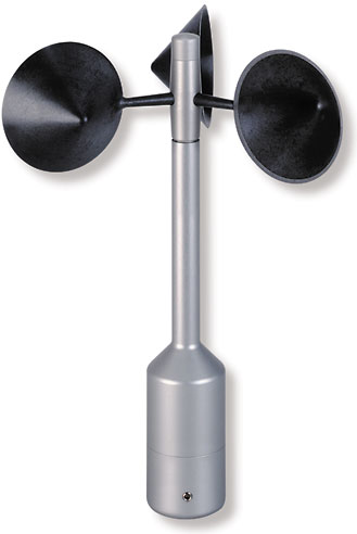
First
Class Anemometer |
first class!
with optional 2 wire
4..20 mA output using EKO22CN-WPfor evaluation of location, and measurement of capacity characteristics of wind power systems.
Fulfills all specifications according the latest requirements (MEASNET , CLASSCUP,
IEC 61400-121-CD)
- optimized dynamic action also with high turbulence-intensity
- minimal over speeding
- low starting values
- high accuracy
- Certified by DEWI and WindGuard
- high survival speed (Certified by DNW)
- excellent cost -performance ratio
1. Range of ApplicationThe wind transmitter is designed for the acquisition of the horizontal component of the wind speed in the field of meteorology and environmental measuring technology. The measuring value is available as digital signal at the output. It can be transmitted to display instruments, recording instruments, data loggers as well as to process control systems. For winter operation the instrument is equipped with an electronically regulated heating, which guarantees a smooth running of the ball bearings, and prevents the shaft and slot from icing-up.
2. Construction and Mode of Operation
A low-inertia cup star with 3 cups, made of carbon-fibre-reinforced plastic, is set into rotation by the wind. The rotation is scanned opto-electronically, and is converted into a rectangular signal. The frequency of this signal is proportional to the number or rotations. Depending on the connection, the output signal ranges between maximal output voltage and ground or a potential (life-zero), lifted by approx. 1,2 v. The supply of the electronics can be effected by dc-voltage of 3,3 v up to 42 v at a very low current consumption. An ac- or dc-voltage of 24 v is intended for the separate supply of the optional heating. In all probability, the heating guarantees a trouble-free function of the Wind Transmitter First Class even under extreme meteorological icing-conditions.
The outer parts of the instrument are made of corrosion-resistant anodized aluminum. Highly effective labyrinth gaskets and o-rings protect the sensitive parts inside the instrument against humidity and dust. The instrument is mounted onto a mast tube; the electrical plug-connection is located in the transmitter shaft.
Order-No. EKO 4.3350.00.000 EKO 4.3350.10.000 with heating w/o heating
Technical Data:
Characteristic Description Measuring range 0,3...75 m/s Measuring instability(w/o calibration) 0,3...50 m/s < 3% of meas. value or < 0,3 m/s Survival speed 85 m/s (max. 30 min.) Permissible Ambient conditions - 50...+ 80°C, all occurring situations of relative humidity (incl. dew moistening) Output signal Form rectangle Frequency 1000 Hz @ 50 m/s Amplitude is supply voltage, max. 15 V Load R > 1 K Ohm (Push-pull output with 220 Ohm in series)
C < 200 nF (corresp. to length typical cable < 1km)Linearity Correlation factor r between frequency and wind speed, r > 0.999 95 (4…20 m/s) Starting velocity < 0,3 m/s Resolution 0,05 m wind run Distance constant < 3 m (acc. to ASTM D 5096 - 96) Inclined flow Measuring value deviation Delta v compared with stationary horizontal flow: Delta v < 1 % conditions: Wind speed v = 8 m/s Voltage: 3,3...42 V DC (galvanic isolation from housing)current: 0,3 ma @ 3,3 V typical (w/o external load) < 0,5 ma @ 5 V (w/o external load) Voltage: 24 V AC/DC (galvanic isolation from housing)Idling voltage: max. 30 V AC, max. 42 V DC Capacity: 25 W 8-pole plug-connection for shielded cable in the shaft(see connecting diagram below) Mounting on mast R 1", for ex. DIN 24411½ " with separate adapter (option) See dimension diagram Mounting on mast R 1", for ex. DIN 24411½ " with separate adapter (option) 0,5 kg IP 55 (DIN 40050) EN 61000-6-2:2001 (immunity)EN 55022:2001, class B (interfering transmission) t <= 20% Turbulence structure (rough country) r <= 0,8d Average deviation from the horizontal flow ð 2° Turbulent flow deviation Delta v turbulent compared with stationary horizontal flow
-0,5% < Delta v < +2%
frequency < 2 HzWind load at 75 m/s ca. 100 N Heating Surface temperature of housing neck > 0 °C, at 20 m/s up to -10 °C air temperature, at 10 m/s up to -20 °
Cusing the THIES icing standard 012002 on the housing neck.Heating regulated by temperature sensor.Electrical supply for opto-electronic scanning Voltage: 3,3...42 V DC (galvanic isolation from housing) current: 0,3 mA @ 3,3 V typical (w/o external load) < 0,5 mA @ 5 V (w/o external load) Electrical supply for heating Voltage: 24 V AC/DC (galvanic isolation from housing) Idling voltage: max. 30 V AC, max. 42 V DC Capacity: 25 W Connection 8-pole plug-connection for shielded cable in the shaft Mounting Mounting on mast R 1", for ex. DIN 24411½ " with separate adapter (option) Weight approx. 0,5 kg Protection IP 55 (DIN 40050) EMV EN 61000-6-2:2001 (immunity)
EN 55022:2001, class B (interfering transmission)